

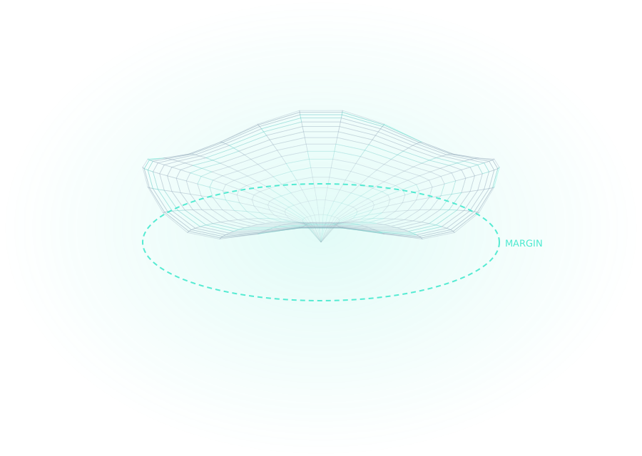
Every CAD system ships with defaults that have to work adequately for everyone. Adequate for everyone means optimal for nobody, and the gap between the default and what your material, mill and cement actually need is paid for in manual corrections, several times a day, forever.
The parameters below are the ones most worth deriving rather than accepting. What follows is how to reason about each. The numbers themselves have to come from your own setup, and anyone who hands you a universal figure is guessing on your behalf.
Cement gap and why it is two numbers
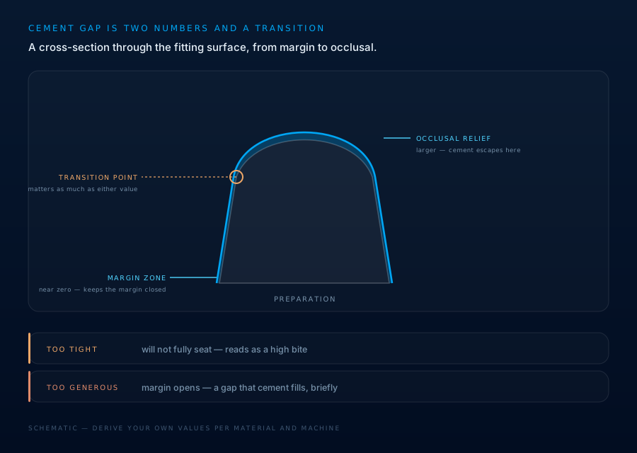
Cement gap is not one setting. It is a space near the margin, usually small or zero, to keep the margin closed, and a larger space above it, giving the cement somewhere to go during seating. The transition point between them matters as much as either value.
Too tight and the restoration will not fully seat, which presents as a high bite that adjusting the occlusion cannot fix. Too generous and the margin opens.
What it depends on: the cement's film thickness, your milling machine's accuracy, the bur diameter at the margin, and the material. A zirconia crown from a five-axis mill and a lithium disilicate from a four-axis unit do not want the same figure.
Minimum thickness is a material property, not a preference
Every material has a minimum below which it fractures in service, and it varies enormously across the ceramics, hybrids and metals you might use in a week.
The trap is that CAD will let you go thinner. It will warn, and it will let you proceed, and the restoration will look correct and fail in six months. Set the minimum per material and let it constrain the design.
If you routinely fight that constraint on the same tooth type, the problem is usually the preparation, not the parameter, which is a conversation with the referring clinician rather than a setting to relax.
Connector cross-sections carry the span
Bridge failures concentrate at connectors, and connector strength scales sharply with height — occlusogingival dimension matters far more than buccolingual width. A connector that is wide and short is much weaker than the same area made tall and narrow.
Cross-section requirements rise with span length and differ by material and by position in the arch. Anterior connectors are constrained by aesthetics and embrasure form as well as strength, which is where the real judgement sits.
The rest of the set, briefly
- Spacer/relief for adjacent contacts — determines whether contacts arrive tight, correct or open, and is a common source of daily manual adjustment
- Occlusal contact strength — whether designs arrive slightly high by intention or already adjusted
- Milling compensation, the software must know your smallest bur diameter, or it will design internal geometry the machine physically cannot cut
- Margin ramp and offset — how the restoration meets the finish line, and how forgiving that is of a preparation with a less than crisp margin
Published starting points
These ranges appear consistently in the literature. They are somewhere to start from, not values to adopt, the right figure for your setup depends on your mill, your bur diameter and your cement, and the only way to know it is to test.
- Cement space, commonly recommended: around 30–60 µm, with 40 µm the most frequent software default
- Cement space for optimal marginal fit: studies cluster around 25–50 µm
- Occlusal relief for zirconia: figures up to roughly 70 µm appear, on the reasoning that the occlusal surface needs more escape volume than the axial walls
- Clinically acceptable marginal gap: broadly 100–200 µm — note this is the accepted outcome, not a value you set
That last distinction catches people. Designed cement space and resulting internal gap are not the same number, and the gap measured in the mouth is routinely larger than the figure entered in the software. Which is exactly why the value has to come from what your machine produces, rather than be copied from anyone, including this article.
How to derive your own numbers
Rather than copying figures, run this once per material and machine combination:
- Design and produce a small batch at the default value
- Record what you had to adjust, and in which direction, on every one
- Change one parameter, produce another batch, record again
- Keep the value that reduced adjustment; move to the next parameter
Tedious, and it takes an afternoon. It also permanently removes an adjustment you were otherwise going to make on every case for years.
Save the result as a named parameter set per material, not as a global change, the whole point is that different materials want different answers.
Planning and design support only. Diagnosis, treatment planning and clinical decisions remain entirely with the treating clinician.